
Introduction
Mold drawings are vitally important documents used in manufacturing and industrial design industries, serving as guides to create molds used to cast or shape various materials. By providing information regarding design, dimensions, and specifications of a mold’s dimensions as well as production processes; mold drawings ensure efficiency during their creation process. Here we explore various commonly utilized mold drawings with their significance to mold design.
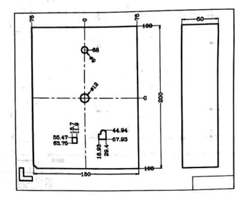
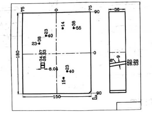
Product Drawing in Mold Design
Product drawings play a central role in mold design as visual depictions of final manufactured goods, providing visual cues of essential details like dimensions, specifications, aesthetics and dimensions of desired end products. Their primary function is to provide guidance in accurately designing molds so as to meet target specifications of final manufactured goods.
Key elements and characteristics of product drawings in mold design include:
Dimensions and Measurements: A product drawing contains precise measurements of its product, such as length, width and height measurements that help determine what size and shape mold must be created in order to create that product. This information is essential in selecting an adequate mold that will produce it successfully.
Specifications: A drawing may include specifications like material requirements, surface finish specifications and tolerance levels that ensure mold design and manufacturing meet with desired product outcome. Such details help ensure an efficient mold production process and product result.
Visual Details: Product drawings may incorporate visual details that accurately portray the appearance and aesthetics of the final product, including textures, contours, surface patterns and any intricate design elements that help shape its final aesthetic. Mold designers use these visual details as guides when developing mold cavities, cores or any other mold components necessary to reproduce that look in production molds.
Product drawings in mold design act as an invaluable communication tool among product designers, mold designers and manufacturers, providing them with a visual reference of what should be expected and facilitating collaboration among all of those involved in its creation process.
Product drawings provide an early opportunity for early identification and resolution of potential design flaws or discrepancies, validating feasibility in relation to mold production while permitting adjustments before proceeding further with mold manufacturing.
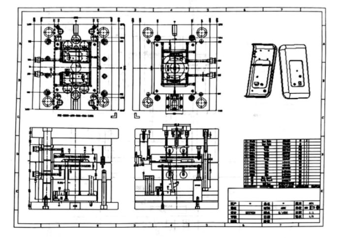
Assembly Drawing in Mold Design
An assembly drawing serves to illustrate the internal architecture of all molds in an assembly set and allows a fitter to find appropriate molds based on this drawing.
Assembly diagrams typically comprise four views of an assembly system; these four views include partial top views of both molds (front mold and rear mold) as well as front view and side views (if necessary). Should four views not sufficiently demonstrate its structure, additional main and side views can be included to reflect reality.
Key elements and characteristics of an assembly drawing in mold design include:
Placement: An assembly drawing clearly demonstrates the arrangement and placement of various mold components, from cavities and cores to alignment of ejector pins, guiding mechanisms, and other auxiliary parts. This ensures all pieces fit seamlessly to create an efficient mold.
Interconnections: An assembly drawing details all of the interrelationships and interactions amongst various mold components. It includes details like mating surfaces, locking mechanisms and fastening methods used to hold together components for a faster production process. An accurate assembly drawing allows manufacturers to ensure their mold stays sturdy during manufacturing.
Clearances and Tolerances: The drawing provides specifications on clearances and tolerances between mold components to allow for proper functioning and movement within the assembly of a mold. This ensures there is enough space for material flow, optimal cooling channels to function optimally and parts to operate without interference from other components.
Mounting and Support Structures: When producing an assembly drawing, mounting and support structures required to hold the mold in place may also be included as details about its base, support plates and any fixtures which provide stability or structural integrity to its assembly may also be provided in detail.
By providing an assembly drawing in mold design, an assembly drawing provides efficient communication among designers, manufacturers and operators as it ensures clear understanding of its structure, component arrangement and overall functionality.
Assembly drawings enable early identification of potential interferences, misalignments or assembly issues during design phase – helping streamline assembly procedures while decreasing errors during production and assuring smooth functioning molds during assembly.


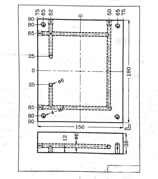
Part Drawing in Mold Design
Part drawings are an integral component of mold design as they focus on individual mold components. Part drawings provide comprehensive details regarding their shape, size and specifications to facilitate precise manufacturing and assembly of mold parts.
Key elements and characteristics of part drawings used for mold design include:
Part Geometry: Drawings depicting part geometry represent mold components like cavities, cores, inserts and other complex features with precision using measurements, contours and surface profiles ensuring accurate reproduction of parts that meet desired specifications.
Material Specifications: Part drawings typically outline material specifications for every component, such as type of material used and hardness/surface treatment requirements if applicable. This ensures mold parts manufactured using quality materials can withstand molding processes to produce high-quality parts.
Tolerance and Fit: Part drawings contain drawings showing tolerances and fit requirements between various mold components to ensure smooth operation and optimal functionality during production. It ensures all pieces fit precisely, permitting optimal functional performance from production molds.
Surface Finish of Mold Components: Part drawings may include specifications regarding the desired surface finish of mold components in order to achieve an ideal texture and appearance of their final molded product. This information can help ensure success when creating prototype molds from an ordered production run.
Part drawings provide mold manufacturers and machinists involved with fabricating mold components an invaluable source of reference, providing vital details necessary for accurately milling, shaping and finishing each part for seamless integration within their assembly.
Part drawings provide invaluable assistance during assembly by aiding mold designers and operators in aligning and fitting all mold components correctly, while simultaneously helping identify any interferences or potential issues during this step, providing time-bound adjustments or modifications where required.

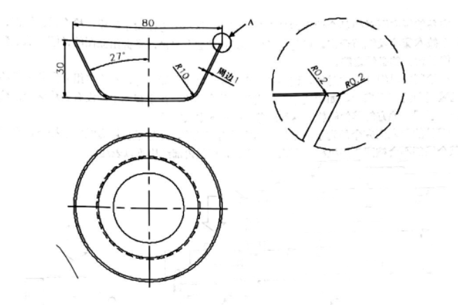
Wire Cut Drawing in Mold Design
Wire cut drawings play an invaluable role in mold design, particularly for molds that utilize electrical discharge machining (EDM) or wire cutting processes to create intricate contours within mold cavities or cores, using EDM or wire cutting processes. Wire cut drawings ensure an exact replication of complex details and features found within a mold design.
Key components and characteristics of wire cut drawings in mold design include:
Details Contours: Wire cut drawings depict intricate contours and forms found within mold cavities or cores requiring wire cutting, including complex curves, angles, and features which cannot be achieved with traditional machining methods.
Dimensions and Measurements: A drawing provides precise sizes and measurements for wire cut features in a mold, to enable wire cutting machines to reproduce accurately the contours and shapes required.
Electrode Placement: Wire cut drawings depict the placement and alignment of electrodes used during EDM or wire cutting processes to erode material and form desired features. Each drawing specifies where and how these electrodes will be utilized during each wire cutting operation.
Tolerances and Surface Finish: Wire cut drawings may specify tolerance requirements for wire-cut features to ensure they conform with desired mold specifications, and also specify any surface finish needed post-wire cutting process.
Wire cut drawings provide mold designers, machinists and EDM operators with essential guidance they require in order to replicate intricate mold details accurately and produce high-quality products from molds. With their precise instructions, they facilitate accurate replication of complex contours and features for consistent production processes that result in quality products being created from these molds.
Wire cut drawings assist the wire cutting process by minimizing errors and increasing efficiency, offering a clear understanding of cutting requirements, eliminating trial-and-error and streamlining overall production processes.
Water Cooling System Drawing in Mold Design
Water cooling is integral to mold design as it regulates temperatures during molding processes. Water cooling system drawings show how cooling channels should be configured within a mold for maximum cooling effectiveness and production optimization. They offer essential information about their design and placement while offering tips to maintain optimal production conditions.
Key components and characteristics of water cooling system drawings used for mold design include:
Cooling Channel Layout: This drawing illustrates the placement and arrangement of cooling channels within a mold, including their path and distribution in order to provide even cooling throughout its entirety.
Channel Dimensions and Geometry: Water cooling system drawings detail the dimensions and geometry of cooling channels in order to enhance flow and effectiveness of cooling process. This includes their cross-sectional shape, diameter and depth which has an effect on flow as well as overall cooling effectiveness.
Locations of Inlet and Outlet Ports for Cooling Water: This drawing shows the locations of both inlet and outlet ports for cooling water to ensure proper flow and circulation throughout the mold, dissipating heat generated during its molding process effectively.
Connection Points: Drawings of water cooling system infrastructures include an outline of where cooling channels interface with external water supply and drainage systems for seamless integration of mold into overall cooling infrastructures. These connection points must ensure effective management of mold growth while cooling.
Water cooling system drawings play an integral part in mold design by encouraging efficient cooling, eliminating uneven cooling patterns or excessive heat build-up issues that might otherwise result in product defects caused by uneven cooling or warping, or helping achieve consistent temperature distribution within a mold which, ultimately, leads to greater quality control and precision with mold output products.
Water cooling system drawings also aid mold designers and manufacturers in optimizing the cooling system by pinpointing potential areas for improvement, helping facilitate analysis of cooling performance and permitting adjustments to channel sizes, layout, or flow rates as necessary.