
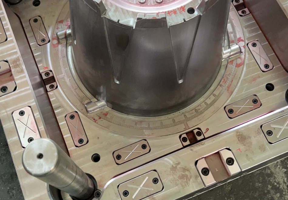
At the mold processing site, it is usually done by dividing edges on the fixed and moving templates of the mold base and using a milling cutter to “open the frame”, and then assembling the mold core into it.
There are two ways to refer, as shown in the following figure.
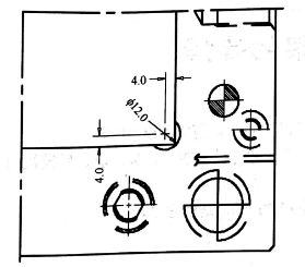
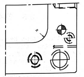
Figure (a) is called the form of clearance angle. Generally speaking, when the size of the mold core is relatively small (less than 1818), a clearance angle can be used; When the size of the mold core is relatively large (more than 1818), the R-angle form in Figure (b) can be used. The R-value is often taken as 8mm, 13mm, 20mm, or 16.5mm, which varies with the size of the mold base. Using an R-angle milling cutter is easy to process, and the corresponding mold should also have rounded corners around it.
The mold core is fixed to the template with screws, preferably M8, and small mold cores can be made with M6 screws. Generally, 4 screws are taken and evenly arranged around the mold core. The specific quantity and specifications should still depend on the size of the mold core. For the convenience of processing, the spacing L of screws should first be considered as a multiple of 20, followed by a multiple of 10 and a multiple of 5. The detailed dimensions are shown in the following figure.

| mold material size A/mm | screw size | quantity/pc |
| <65*65 | M6 | 2 |
| 65*65<A<95*95 | M6 | 4 |
| 95*95<A<140*140 | M8 | 4 |
| 140*140<A<200*200 | M10 | 4 |
| 200*200<A<300*300 | M12 | 4~6 |
| >300 | M16 | 6~8 |