1. The cooling channel is processed by a twist drill, and the diameter of the cooling channel can be determined by selecting the drill bit. Commonly used waterway diameters are Φ8mm and Φ10mm, Φ6mm, and Φ12mm are rarely used. The diameter specifications in the molded waterway should be as consistent as possible to facilitate processing.
2. For automatic forming molds (for horizontal injection molding machines), it is best not to set the water delivery nozzle on the top of the mold, as shown in the figure below. In order not to cause obstacles to the automatic manipulator operation, at the same time, if the water nozzle is installed on the top of the mold, the coolant will easily flow into the cavity when disassembling and transporting water; it is not good to install the water nozzle at the bottom of the mold. The pouring system condensate may hang on the water pipe and cannot fall off. Therefore, it is best to install the water nozzle on the back of the injection molding machine, that is, on the other side of the operator, so as not to affect the operator’s work.

3. Under the premise of ensuring the mechanical strength of the steel material, the water should be evenly arranged along the product and the distance to the product should be kept consistent to enhance cooling and make the mold temperature uniform; the distance between the water and the cavity should not be too far or too close. Too far will affect the cooling effect, and too close will affect the strength of the mold, usually the margin is 10~18mm. The center-to-center spacing between waterways should be kept at about 5 times the diameter of the waterways, as shown in the figure below.

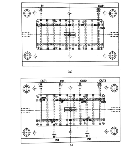
4. Minimize the water temperature difference between the inlet and outlet of the transported water. This requires the waterway flow to be as short as possible, and if the water transport is too long, it will inevitably cause a large temperature gradient change, resulting in a higher temperature at the end of the water transport, thereby affecting the cooling effect. The water transport can be divided into several independent circuits to increase the flow of coolant, reduce pressure loss and improve heat transfer efficiency. As shown in figure a below, there is only one group of water channels in the figure, which will cause uneven cooling of the mold and poor effect. In figure b, three sets of water channels are designed, so that the mold can be cooled evenly and the effect is better.
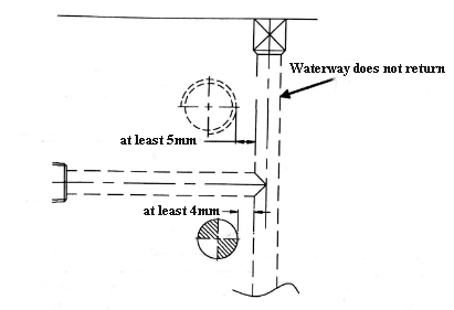
5. The distance between water delivery and inserts and thimbles should be kept at least 4mm; the distance between water delivery and screws should be at least 5mm; the water delivery should not have too long a dead angle, so as not to affect the effect due to the backflow of cooling water. As shown below