

Plastic mold is a tool for the production and molding of plastic products. The principle of plastic mold is to inject a hot, melted plastic material into the mold through an injection molding machine, where it is cooled to form a molded plastic product. The structure of a plastic mold can vary depending on the plastic material, the shape of the product, and the type of injection molding machine, but ultimately the basic structure is the same.
Distinguished by functional structure
A complete plastic mold is generally composed of feed system, molding system, cooling system, vent system, ejection, and guide system, of which the most important are the pouring system and molding system, as these two parts are in direct contact with the plastic and can be adjusted to the plastic and the product.
Feed system
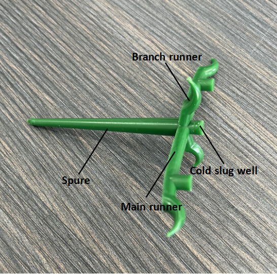
The channel that directs the plastic from the injection molding machine nozzle to the mold cavity is called the feed system, which consists of sprue, runner, gates, and cold slug well.
Molding system
The system that directly forms the shape and size of the product is called molding system and consists of cavity plate, core plate and cavity, core, insert, core pins, etc. The most important of these are cavity and core. Cavity forms the shape of the outer surface of the product and the core forms the inner surface of the product. Depending on the production process and manufacturing requirements, these two main parts are sometimes made up of several inserts as a whole, or inserts may only be used in difficult-to-machine locations or in parts that are easily damaged.
Cooling system
It is generally designed to meet the temperature regulation system of the mold for injection molded products. The common cooling system is mainly designed to make cooling water-ways inside the mold and use water to circulate between the channels to maintain the mold temperature; if it is for heating then the corresponding heating elements are installed around or inside the mold.
Vent system
Vent system is designed to remove the air from the cavity inside the mold and the melt of the plastic material to the outside of the mold during the product-forming process. Its main purpose is to prevent or reduce molding defects such as scorching or air trap marks on the surface of the product.
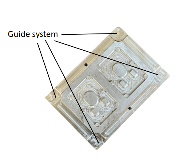
Ejection and guide system
Ejection system is that the product is molded inside the mold. After the mold is opened, the ejection parts eject the product from the mold under the action of injection molding machine, thus completing an entire injection molding production cycle. Common ejection methods include pin ejection, sleeve ejection, bar ejection, and stripper ejection. Ejection system is generally composed of ejector pin, ejector plate, return pin, return spring, and other components.
Guide system is set up to ensure that mold is in the correct direction when opening and closing. In general, four sets of guide pillars and guide bushes are most commonly set up at the corners of mold to form guide system. In addition, there are also located blocks and guide plates.
Mold structure/component terms
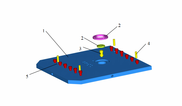
Top plate
| NO. | TERM | ABBREVIATION |
| 1 | Top Clamping Plate | T-C Plate |
| 2 | Locating Ring | LR |
| 3 | Sprue Bush | SB |
| 4 | Dowel Pin | / |
| 5 | Set Screw | / |
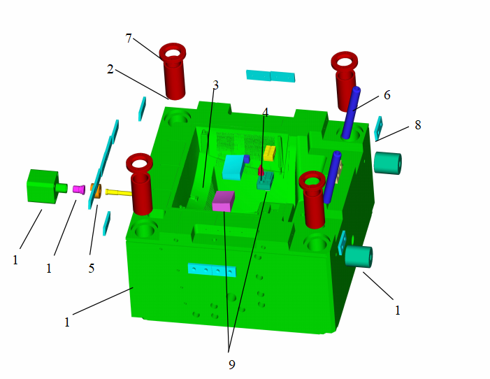
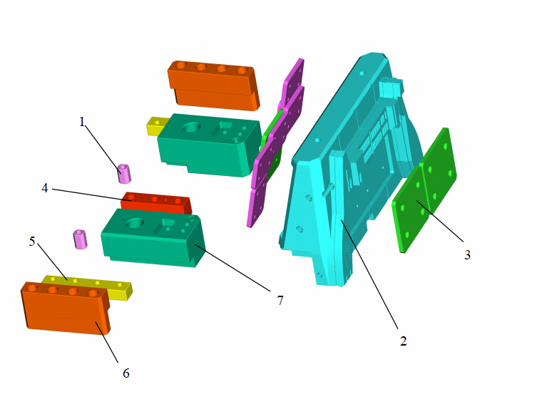
CAV. Plate
| NO. | TERM | ABBREVIATION |
| 1 | Cavity plate | Cavity Plate |
| 2 | Guide Pin Bush | GP-Bush |
| 3 | Cavity Core | Cavity Core |
| 4 | Core Pin | Core Pin |
| 5 | Slide Core | Slide |
| 6 | Angular Pin | AP |
| 7 | Stroke Washer | / |
| 8 | Wear Plate | / |
| 9 | Insert core | / |
| 10 | support pin | / |
| 11 | Hydraulic Cylinder | / |
| 12 | Hydraulic Link | / |
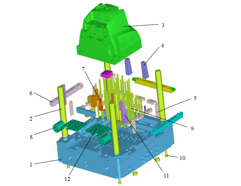
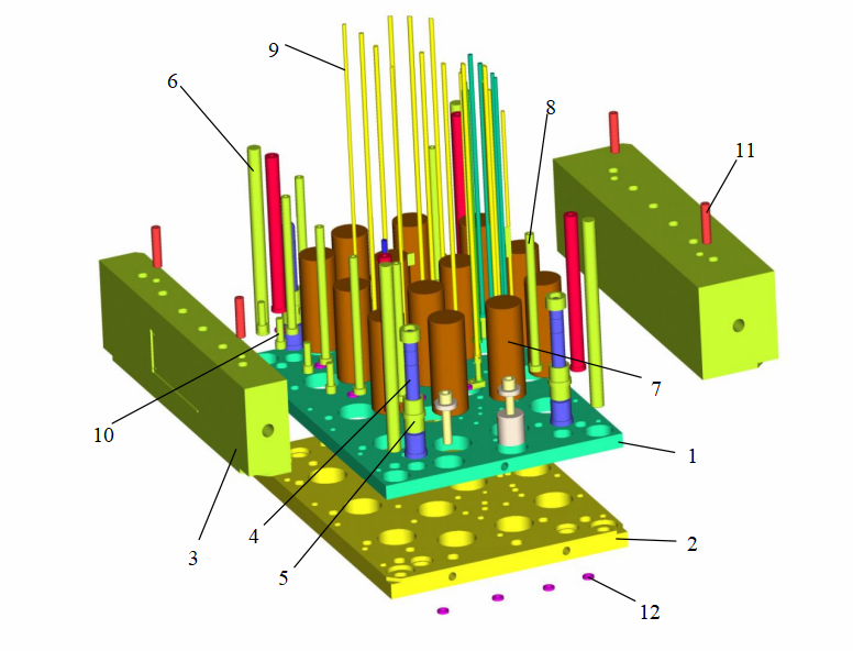
Core Plate
| NO. | TERM | ABBREVIATION |
| 1 | Core plate | Core Plate |
| 2 | Guide Pin | GP |
| 3 | Core | Core |
| 4 | BE-CU Core | Hit75 |
| 5 | Locking Block | LB |
| 6 | Ejector Block Bar | EBB |
| 7 | Core Piece | / |
| 8 | Support pin | / |
| 9 | Baffle Plate | / |
| 10 | Set Screw | / |
| 11 | Insert core | / |
| 12 | Wear Plate | / |
Ejector plate
| NO. | TERM | ABBREVIATION |
| 1 | Ejector Plate (A) | EJ-Plate A |
| 2 | Ejector Plate(B) | EJ-Plate B |
| 3 | Spacer Block | Spacer Block |
| 4 | Ejector plate Guide Pin | EGP |
| 5 | Ejector plate Guide Bush | EGP-Bush |
| 6 | Return Pin | RP |
| 7 | Support Pillar | SP |
| 8 | Ejector Sleeve | ES |
| 9 | Ejector Pin | EP |
| 10 | Bolt | / |
| 11 | Dowel Pin | / |
| 12 | Stop Pin | / |
Bottom plate

| NO. | TERM | ABBREVIATION |
| 1 | Bottom Clamping Plate | B-C Plate |
| 2 | Limit Switch | L/W |
| 3 | Bolt | / |
| 4 | Set Screw | / |
| 5 | Dowel Pin | / |
| 6 | Retaining Block | / |
Slide core
| NO. | TERM | ABBREVIATION |
| 1 | Slide Core Puller Block | (C/REAR) |
| 2 | Slide Core | Slide |
| 3 | Wear Plate | / |
| 4 | Guide rail | / |
| 5 | Guide plate | / |
| 6 | Guide Track | / |
| 7 | Link Block | / |