I. Introduction
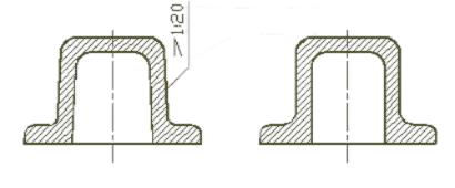
Draft angle (sometimes known as taper angle ) refers to the degree of an inclined surface on a part or mold cavity which allows smooth and effective removal from its mold cavity. Measured in degrees, draft angles help ensure successful part ejection from their respective mold cavities.
Draft angle in injection molding serves many functions. Primarily, it aids the easy release of parts from their molds during ejection by providing gradual disengagement between parts and mold walls during this phase. Without it, parts would encounter resistance that might force production delays or jam them inside their mold – leading to production delays, mold damages or higher costs overall. We will explore this concept further herein in this article and its significance in producing successful part production.
II. Relationship between Draft Angle and Mold Release Actions
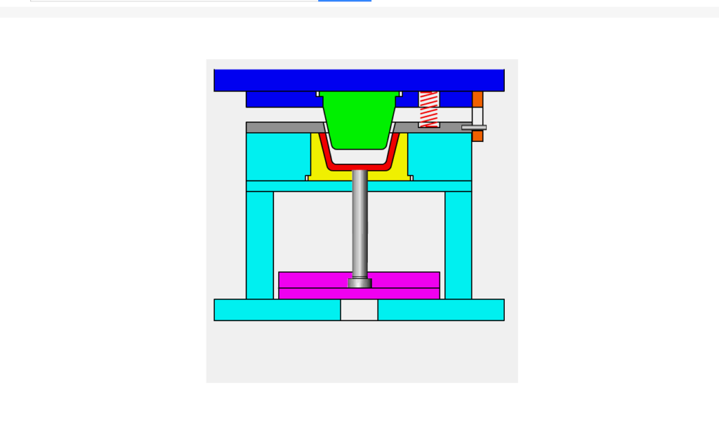
As soon as a mold opens, its draft angle ensures gradual disengagement between the part and mold walls, helping ensure smooth release without sticking or binding issues. Without adequate draft angles in place, resistance could arise that causes delays or damages either to production delays or parts or molds.
Draft angle can significantly impact the force required to release molds. A larger draft angle reduces friction and drags between parts and mold, leading to decreased ejection forces and faster cycle times and production efficiency. Conversely, an inadequate draft angle may increase this force which in turn puts stress on parts while altering their dimension’s accuracy.

III. Factors to Consider When Choosing a Draft Angle
As part of selecting an injection molded part draft angle, numerous design considerations come into play. These ensure that it fits in with both part design requirements and manufacturing process requirements, with various key design issues for injection molded parts as outlined below:
Part Geometry
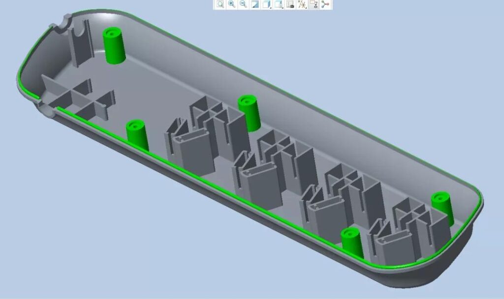
When selecting an ideal draft angle for any part’s design, its overall shape and complexity play an integral part. Parts with straightforward geometries require less aggressive draft angles while complex designs like deep draws, recesses or intricate details require larger draft angles in order to successfully eject.
Wall Thickness
As previously discussed, wall thickness can have an enormous influence on draft angle selection. Thicker walls tend to require larger draft angles for smooth release while thinner ones might permit smaller draft angles – therefore it is imperative that analysis be conducted of your part’s wall thickness distribution in order to optimize draft angles appropriately.
Material Selection
Differing materials exhibit different degrees of shrinkage and mechanical properties during injection molding processes, impacting draft angle selection. When choosing thermoplastic materials as candidates for molding injection molding applications, its specific properties such as its shrinkage rate, flow properties, or flexibility should all be taken into consideration when choosing their appropriate draft angle.

Surface Finish Requirements
The surface finish requirements of your part play a large role in choosing its draft angle. Smooth or polished surfaces typically need smaller draft angles for their integrity to remain uncompromised during release; on the other hand, textures or patterns require larger draft angles so as not to alter or compromise desired textures during their release process.
Ejection and Tooling
When choosing the draft angle in injection molding processes, consideration must be given to both ejection system and tooling used during production. Factors like mechanism type, pin location and complexity of mold design all impact draft angle requirements – therefore collaboration between design engineers and mold makers is vital in order to guarantee compatibility between draft angle selection and the ejection system used.
Parting Line Placement
The placement of parting lines defines where mold sections meet, which has an effect on their visual presence on a finished part. Positioning them strategically can reduce visibility while improving aesthetics overall.
IV. Impact of Wall Thickness on Draft Angle Selection
Draft Angle and Thick Walls
Parts featuring thicker walls usually need larger draft angles in order to facilitate easier and faster part ejection without risk of sticking or damage during injection molding. Additionally, more heat retention from thicker sections means greater resistance during ejection; by employing larger draft angles during molding processes more evenly distributed release forces may help ensure smoother part ejection with reduced risk of sticking or breaking off at its edges.
Draft Angle and Thin Walls
Components with thinner walls can benefit from lower draft angles due to faster cooling times during molding; this reduces risk of friction-related issues during ejection and ensures easier release from molds with thinner sections, thus decreasing any chance of distortion or damage during part release. It is still necessary, though, to have sufficient draft angles so as to guarantee smooth release from molding processes without distortion or part damage issues arising during release.
Wall Thickness Distribution
Wall thickness distribution within a part can affect draft angle selection. Sections with differing wall thicknesses may require different draft angles in order to provide optimal ejection and prevent defects; gradual transitions among different wall thicknesses can help ensure consistent draft angles throughout.
Differential Shrinkage
As part of the molding process, different wall thicknesses may experience differing amounts of shrinkage that results in differential shrinkage that causes warping or distortion if overlooked when setting draft angles, leading to deformed parts or warped components. Anticipating differential shrinkage effects is vital when setting draft angles because it reduces risk associated with part deformations.
Structural Integrity
Wall thickness can play an integral part in ensuring structural integrity of parts. Thicker walls offer greater strength and rigidity while thinner ones offer flexibility and cost savings. When selecting draft angles it is key to balance desired structural requirements with those related to ejection to ensure successful production of functional, dimensionally stable parts.
V. Considerations for Deep Draw, Recessed Surface Features, and Complex Geometries
Deep Draw
Components that feature deep draw features, such as tall or elongated sections, require special consideration when setting their draft angle. The depth of draw may interfere with release from molds; larger draft angles often help facilitate smooth ejection with minimal distortion or damage during removal of deep draw features from their molds.
Recessed Surface Features
When creating parts with recessed surface features such as pockets, ribs or intricate details that present difficulty for mold release, such as pockets or intricate details can present unique challenges in terms of draft angle design. It should allow for the successful release of such features without creating cosmetic defects or interfering with adjacent components – thus helping ensure their replication in the final part.
Complex Geometries
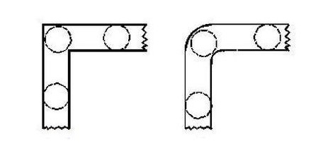
Parts with complex geometries such as curves, undercuts or multiple intersecting surfaces require careful draft angle planning in order to meet their complex geometry requirements. Each surface and contour must be evaluated to establish an acceptable draft angle; sometimes this means altering the minimum draft angle or angles across regions of a part to ensure optimal mold release and ease of mold.
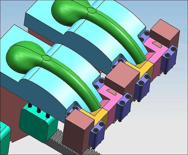
Undercuts and Side Actions
Draft angle selection can become increasingly complicated when dealing with features requiring side actions such as undercuts. Undercuts may impede part ejection, leading to production issues; side actions or additional mold components can help facilitate their ejection but this often requires specific draft angle adjustments and coordination with part geometry to facilitate.
Mold and Tooling Considerations
For deep draw, recessed surface features and complex geometries which require additional mold actions such as slides, lifters or rotating cores in order to facilitate proper part ejection, additional mold actions may need to be added, such as slides or lifters or rotating cores if proper part ejection occurs. These considerations should be included into draft angle selection process in order to meet design and tooling specifications for an efficient production environment.
VI. Balancing Draft Angle with Parting Line and Mold Opening
Parting Line Placement
The parting line serves as the boundary between mold halves from which parts can be released from their molds and should be carefully placed so as to reduce its effect on aesthetics and functionality of parts released by this line. Draft angles must also be designed in concert with this parting line in order to facilitate easy part release without visible parting line marks or defects obstructing their release from molding processes.
Mold Opening
For optimal mold opening results, injection molding draft angle selection must align with its opening mechanism. As the mold opens gradually, draft angles support gradual release of parts from mold cavities through gradual opening mechanisms. It is imperative that sufficient clearance be allowed during opening to avoid interference or damage to either part or mold components.

Mold Design and Complexity
The complexity and presence of additional mold components such as slides, lifters, or rotating cores may affect draft angle selection. Such components enable undercuts or features requiring side actions to be released more smoothly from molds; draft angles must therefore be selected in coordination with mold design to avoid conflicts during part release and avoid complications that might impede operation.
Mold Materials and Surface Treatments
Selecting mold materials and surface treatments can have an impactful influence on draft angle requirements. Different mold materials have different coefficients of friction which affect part release ease; additionally, certain coatings or textures require specific draft angle considerations in order to preserve integrity during part ejection.
Part Design Constraints
Draft angles should be chosen carefully to meet all design constraints of a part’s overall design constraints, including dimensions requirements, structural considerations or functional features. Any selected draft angle must not compromise functionality of the part nor cause dimensional inaccuracies that lead to any undesirable inaccuracy issues.
VII. Rule of Thumb for Draft Angle Selection
1. A draft angle of at least half a degree per side should serve as a general guideline in draft angle design, translating to at least a draft angle of one degree overall – that means an increase of approximately half a degree with every 25.4 millimeters (1 inch of depth). This rule helps ensure adequate draft angles to facilitate part release without risking sticking or damage and helps promote overall part quality and productivity.
2. Consider Wall Thickness: Although the half-degree rule provides an easy starting point, it’s essential that wall thickness be factored into any draft angle calculation. Thicker walls may require higher draft angles due to increased material volume or shrinkage upon cooling while thinner walls might allow for smaller draft angles but special care must be taken during ejection processes to avoid issues with material deflation or issues when printing is complete.
3. Material Characteristics: When applying this rule of thumb to injection molding processes utilizing thermoplastic material injection molding processes, its specific characteristics such as friction coefficient or shrinkage rates must also be taken into consideration. Some materials have higher coefficients of friction or greater shrinkage rates which might necessitate modifications to draft angle to ensure successful part release.
4. Practical Testing and Validation: While using rules-of-thumb can provide a solid starting point, it is critical that any selected draft angle be validated through practical testing and analysis. Prototypes, mold trials or simulation software can all help assess its functionality before going full-scale production.
VIII. Calculation Approaches for Draft Angle in Injection Molding
Geometric Calculations
One approach for calculating draft angle involves conducting a geometric analysis of part design. This involves taking into account features like wall thickness, depth and shape to ascertain an acceptable draft angle for part ejection success. Geometric calculations use mathematical equations and geometric principles in order to derive this figure.
Mold Flow Analysis
Mold flow analysis uses simulation-based software to simulate and assess how molten plastic flows within a mold cavity, giving insight into its filling pattern, cooling rate and subsequent part ejection. By simulating various draft angles this software identifies an ideal angle that minimizes flow restrictions while still producing quality parts and allows efficient ejection.
Finite Element Analysis (FEA)
Finite Element Analysis is a computational method using numerical modeling techniques to examine how parts behave under various loading conditions. By employing this analysis to mold design, engineers can simulate how various draft angles impact structural integrity, deformation and stress distribution for their part – helping determine an ideal draft angle that maintains functionality requirements while permitting mold release without failure.
Mold Trials and Prototyping
Mold trials and prototyping provide practical insights into draft angle requirements. By designing test molds with different draft angles, designers can observe ejection processes for any issues to fine-tune draft angles accordingly. Mold trials provide real-world validation of calculated draft angles enabling adjustments or improvements as necessary.
Expert Knowledge and Experience
Injection molding specialists and mold makers possess invaluable expertise when selecting draft angles. Their understanding of materials, mold design and manufacturing capacities complement calculation approaches; consulting experts from these fields may offer additional insights while guaranteeing the selected draft angle meets best practices and industry standards.

IX. Best Practices for Draft Angle Selection
Minimum Draft Angles
As a general guideline, draft angles between 1 to 2 degrees should provide adequate part release without risking sticking or damage during ejection. However, certain factors like material characteristics, part geometry or surface finish requirements could necessitate larger draft angles.
Larger Draft Angles for Deep Draw or Larger Parts
When producing parts with deeper cavities or larger dimensions, ideally it would be wiser to increase their draft angles by two to three degrees on either side. A draft angle of this magnitude or greater should ensure smooth ejection while decreasing distortion or damage risk; an angle between 2-3 degrees per side could prove adequate in such instances.
Consider Wall Thickness
Wall thickness also plays a part in selecting an optimal draft angle for parts, with thicker walls necessitating larger draft angles to accommodate material volume changes during cooling; thinner walls may allow for tighter draft angles but must still be approached with caution to prevent issues during ejection.
Surface Finish Requirements
When setting draft angles for mold releases, one must consider their desired surface finish requirements for their part. A smooth surface could require an increase in draft angle so as to avoid marks or defects caused by the process; while rougher finishes and patterns could permit smaller draft angles.
Material Selection
Different thermoplastic materials have different coefficients of friction and shrinkage rates that can influence draft angle requirements; materials with higher coefficients of friction or greater shrinkage rates may require larger draft angles in order to guarantee successful part release.
Testing and Validation
Testing is essential when selecting draft angles; prototyping or mold trials provide designers with an ideal way to monitor ejection processes, identify any sticking points and make necessary modifications to draft angle settings.
Consultation with Injection Molding Specialists
Working closely with injection molding specialists can offer invaluable expertise when selecting draft angles. Doing so ensures the selected draft angle aligns with industry best practices, manufacturing capabilities and manufacturing best practices.

X. Conclusion
Draft angles play an integral part in producing quality injection-molded parts. By understanding their purpose and following best practices for selecting them, designers can optimize the injection molding process and produce parts with excellent surface finishes, dimensions accuracy, and efficient mold releases.